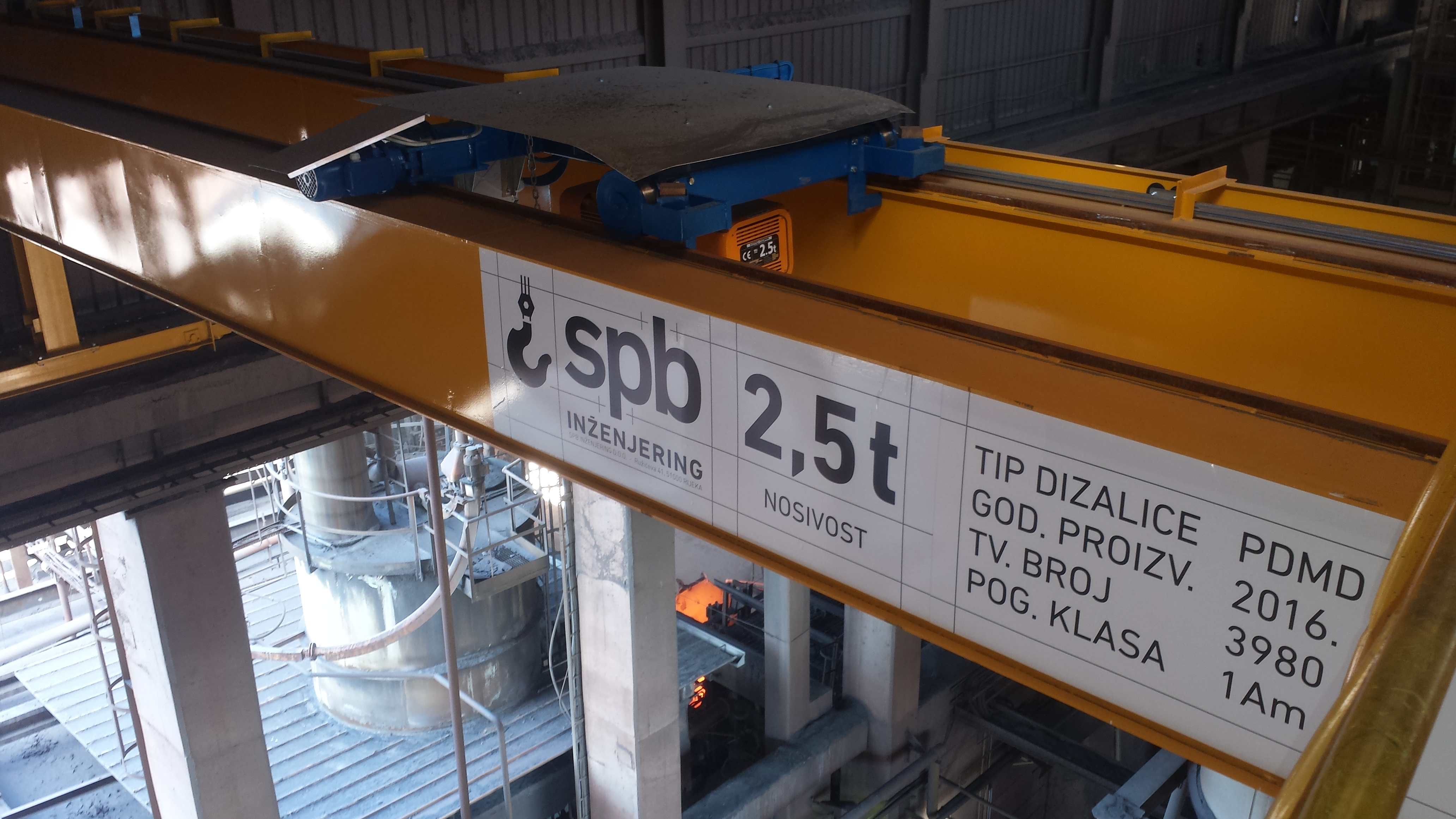
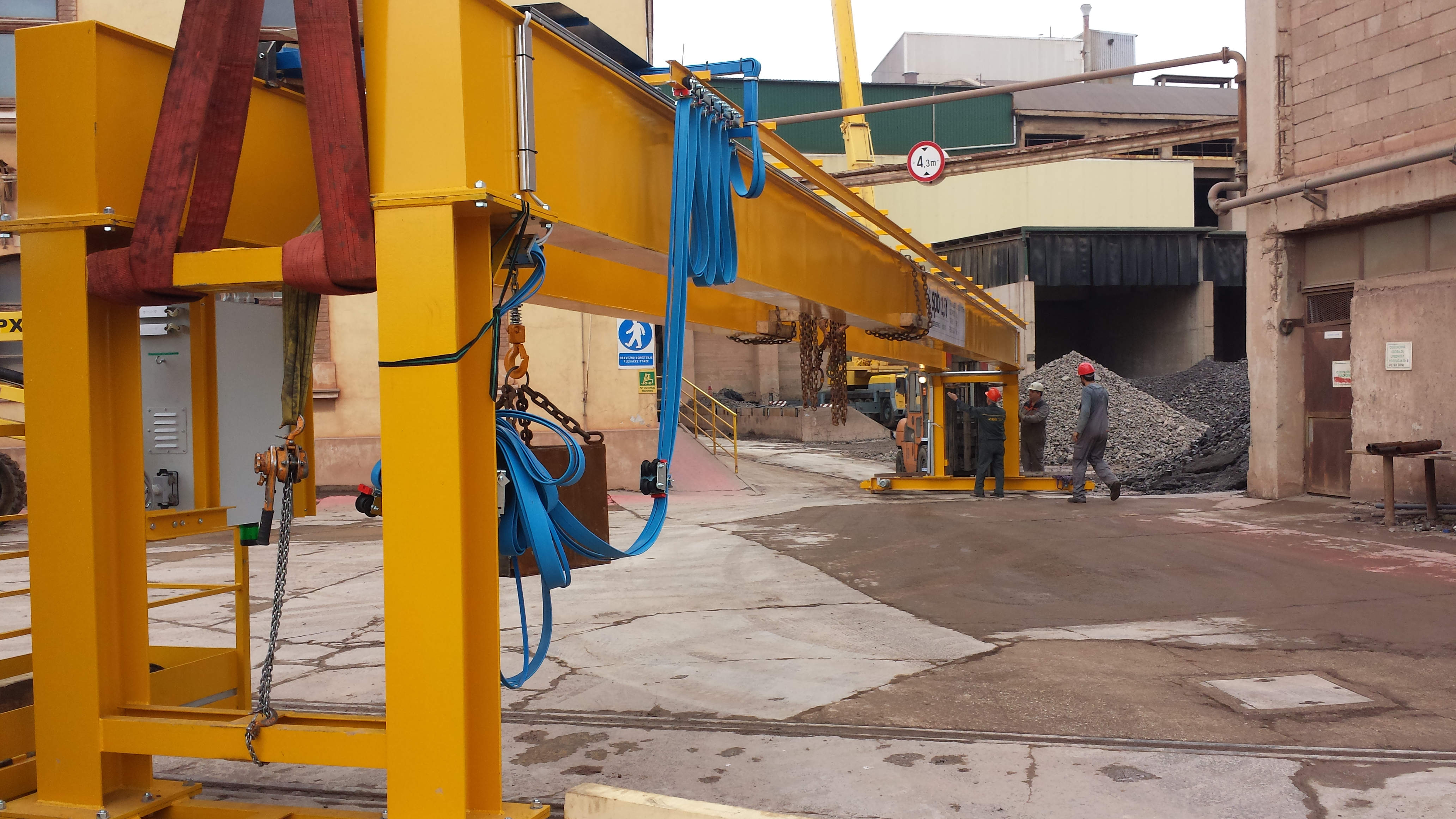
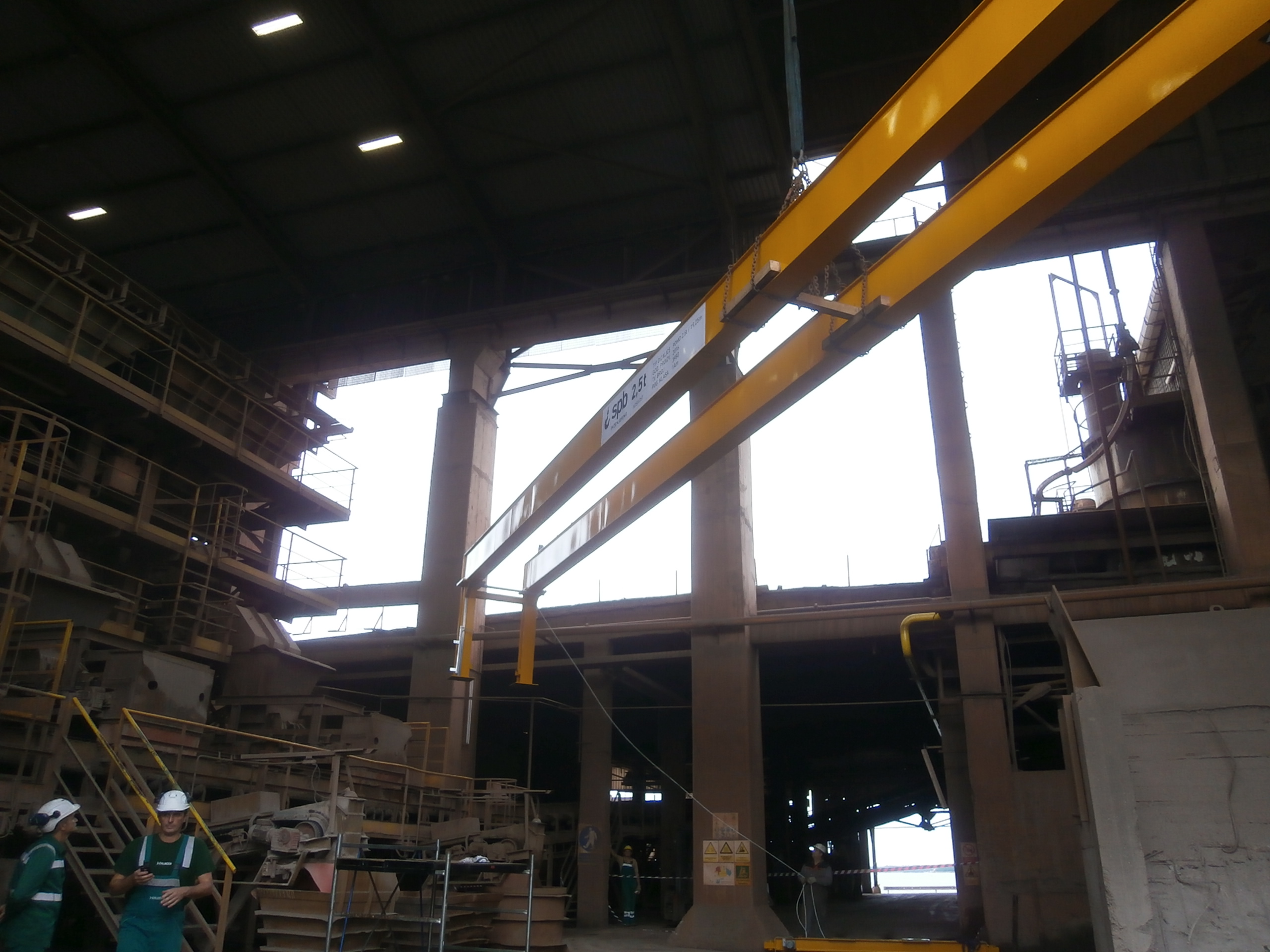
Portal double-girder bridge crane PDMD 2,5 t / 19,25 m
PROJECT NAME: Portal double-girder bridge crane PDMD 2,5 t / 19,25 m
INVESTOR: Calucem Ltd.
LOCATION: Pula
YEAR OF PRODUCTION: 2016.
TECHNICAL CHARACTERISTICS:
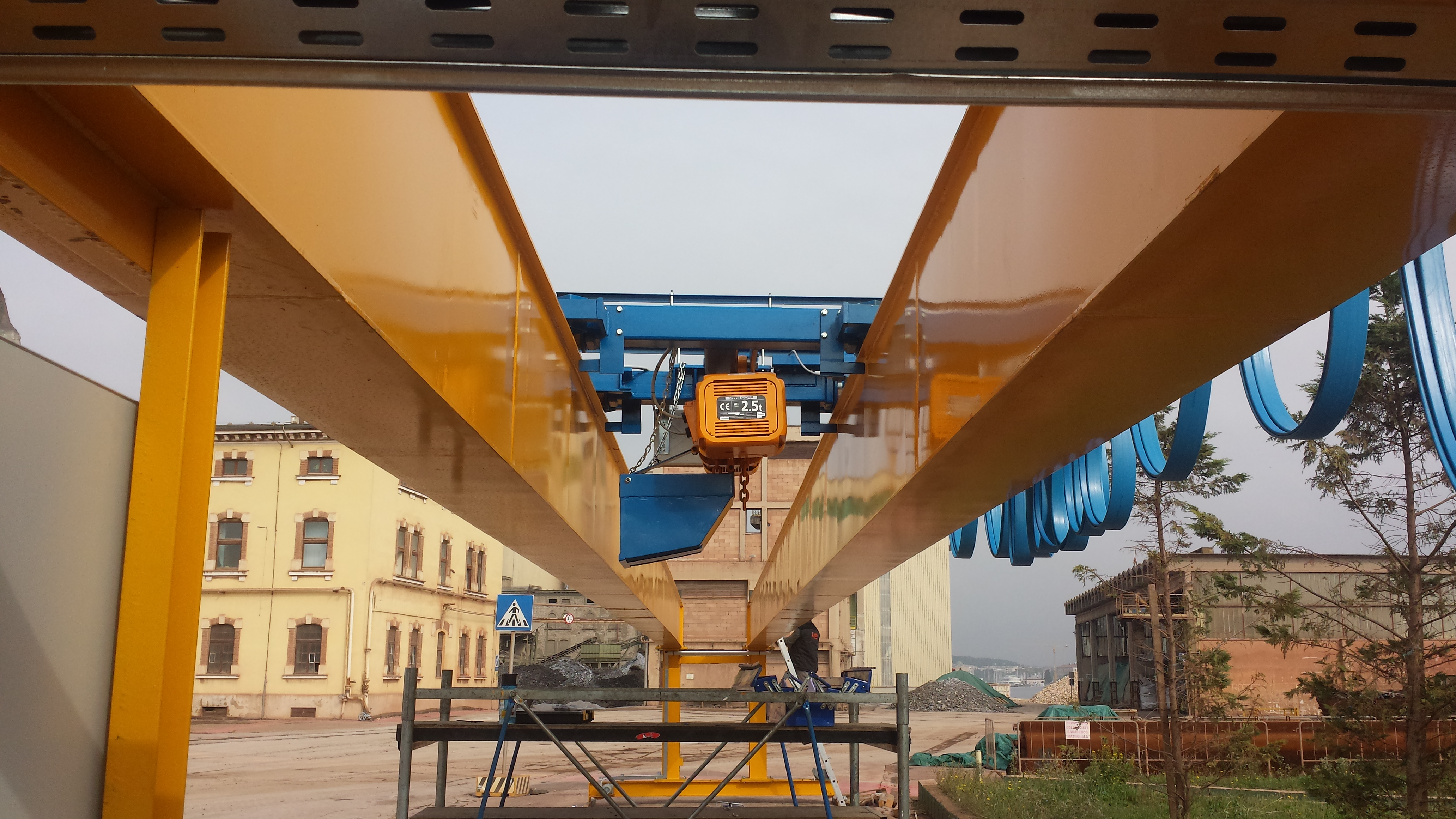
- maximum crane capacity: 2,5 t
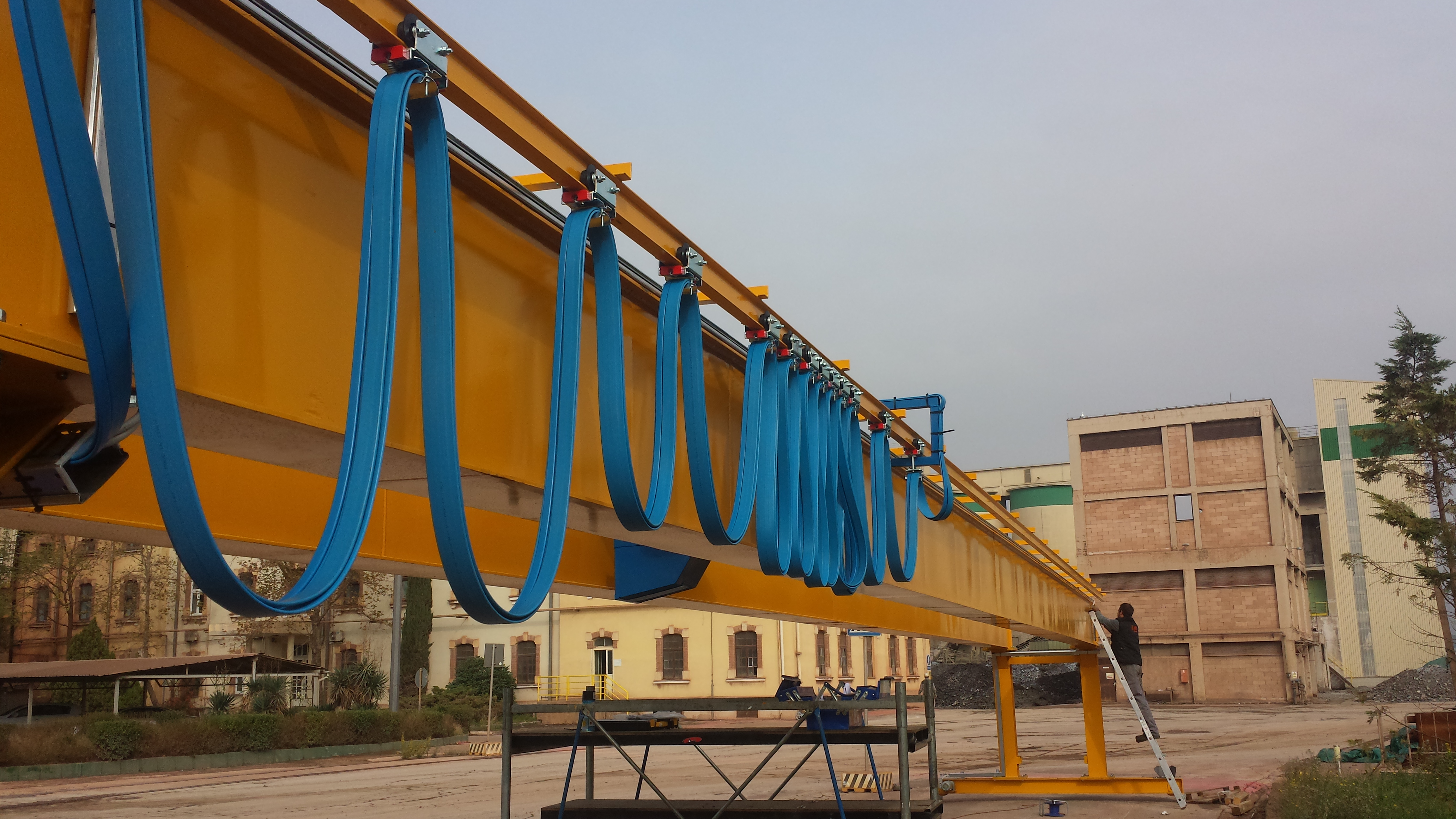
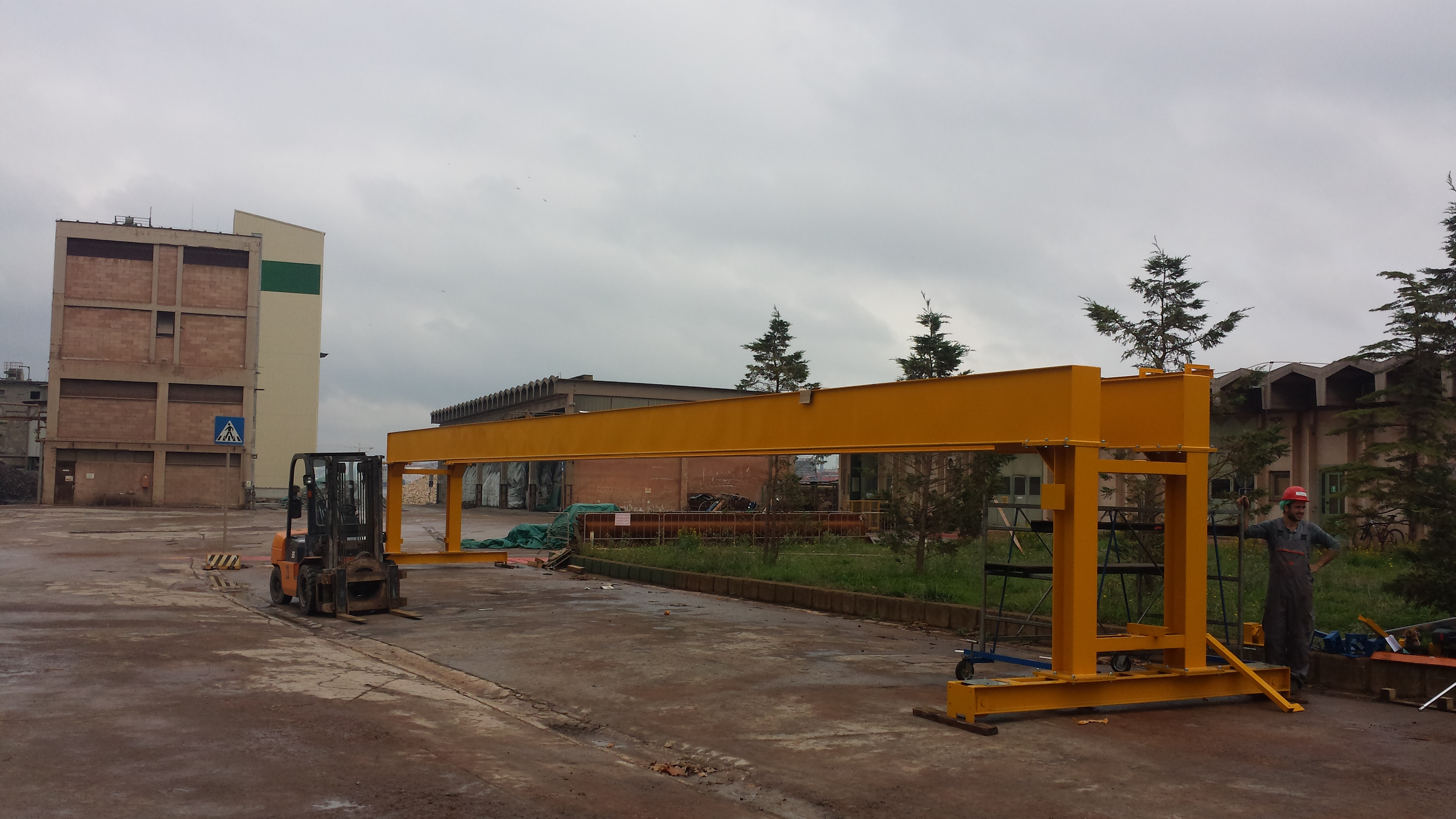
- bridge span: 19,25 m
- lifting height: 17,253 m
- load lifting speed (frequency controlled): 6,6/1,1 m/min
- hoist speed (frequency controlled): 16/4,8 m/min
- bridge travel speed (frequency controlled): 16/4,8 m/min
TECHNICAL DESCRIPTION:
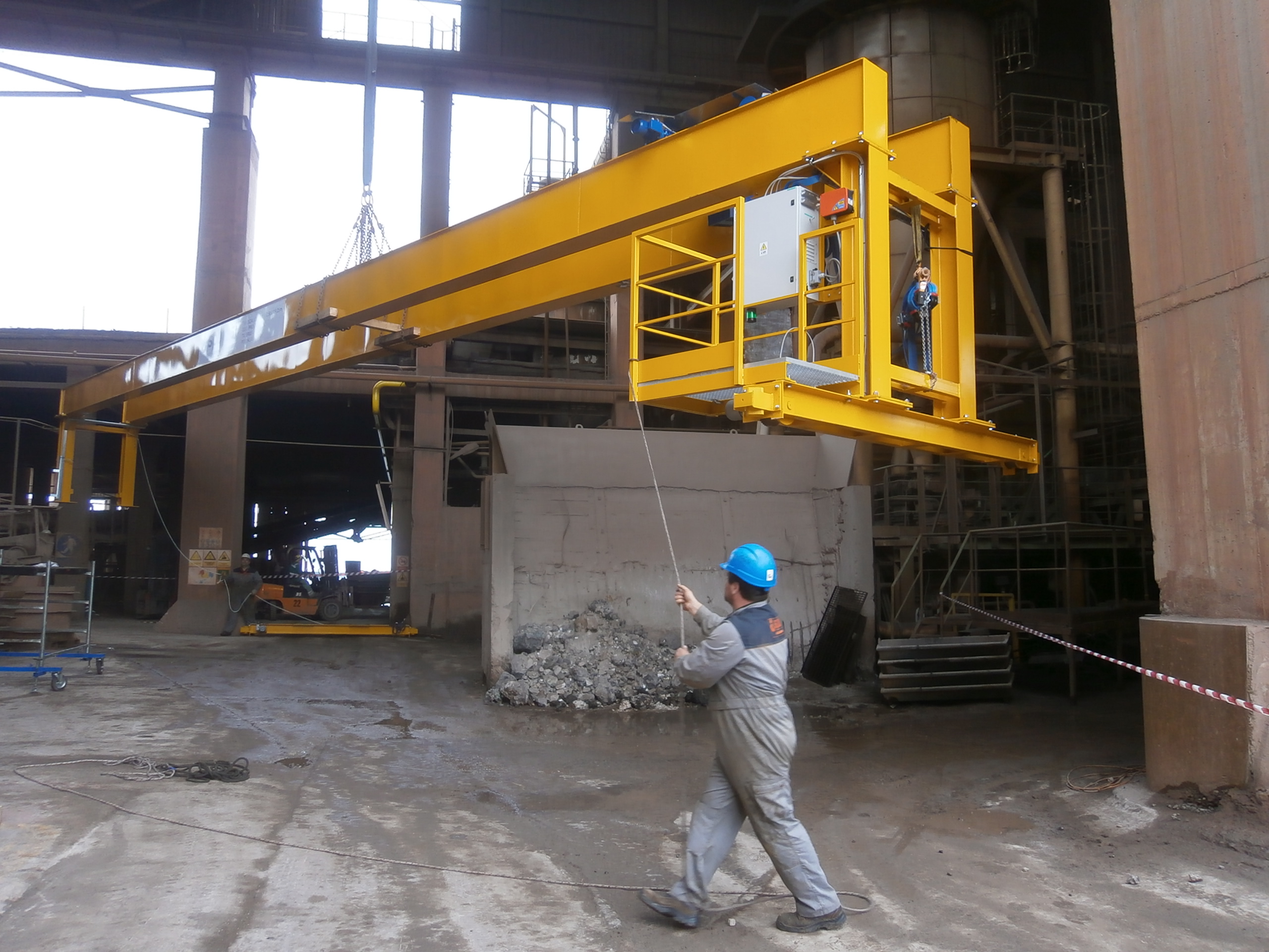
For the needs of the investor, Calucem Ltd., a project of a portal double-girder bridge crane was made. The maximum load capacity of the crane is 2,5 t and the span of the bridge is 19,25 m. The crane is mounted on the existing crane tracks in the production hall. A new crane is being installed between the existing bridge cranes.
All working movements of the crane: driving the bridge, suspended hoist and lifting/lowering the load are electrically driven in two speeds and the control is performed using frequency converters.
As the crane moves along the crane track with the existing bridge cranes, the crane track is fitted with steel bumpers.
The crane is controlled via a radio remote control, and a suspended control button with reduced voltage is provided as a backup control.
Given the conditions and frequency of operation, the crane is classified in I. drive class according to HRN M.D1.020, which roughly corresponds to group M4 according to ISO 4301/1 (or group 1Am according to FEM 1.001), for mechanisms.
The steel structure of the bridge crane basically consists of two main girders, two portals and two end carriages, interconnected by screw joints.
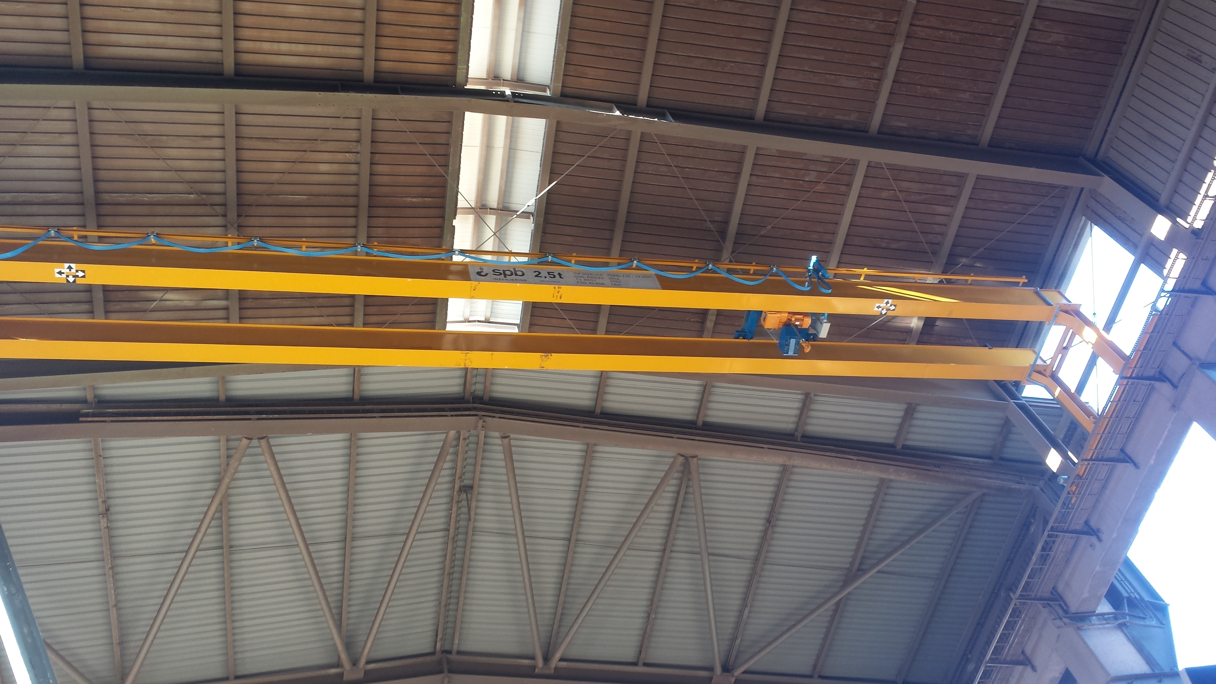
The main girders of the portal double-girder bridge crane are designed as box girders with a cross section of a total length of 19480 mm. The internal stiffeners of the main girder are made of 6 mm thick sheets and are welded at 1000 mm spacing. The stiffeners are not welded to the lower (tensile) belt plate.
At the ends of the main girders, flange plates are welded to the lower belt plate, through which a connection to the portals is made by means of a screw connection, each one to one end of the main girders. At the bottom of each portal there is also a flange plate that rests on the end carriages and their connection is also made by means of a screw connection.
A 30x30 mm square rail is welded to the upper belt plate of both main girders, which is used for driving trolleys with a 2,5 t hoist. The rails are welded along the inner edge of the upper belt plate, ie in the bisector of the side plate of the main girder. At the ends of the rails, rigid bumpers are welded, which serve to limit the movement of the hoist.
The electrical equipment of the crane consists of:
- electric motor of the lifting mechanism with brake,
- electric motors with brakes of suspended hoist,
- two electric motors with brakes for driving the bridge,
- control cabinet,
- limit switches for switching off the lift drive, the hoist drive and the bridge drive,
- radio remote control,
- suspended control button with reduced voltage,
- main switches, and
- power and control cables within the crane itself.